This article is about a sound generator made with ten 555 timer oscillators. Because I used dual 555 timers (556 timer ICs (integrated circuits)), I used five ICs instead of ten.
Figure 1: Device.
You can see the circuit working in this video:
Step 1: Design the Circuit
I have drawn the circuit in PSpice software version 9.1 (student edition).
I designed the circuit with 22 nF and 10 nF capacitors when I could have used one 33 nF capacitor because this is what was available at the local electronics store.
Figure 2: Design the Circuit.
The oscillation frequency is equal to:
f = 1.44 / ((R1a+2×(R1b+R1c)) × Cf)
(Where: Cf = Cf1a + Cf1b)
The circuit is designed to mix sounds from ten 555 timer generators with a resistor mixer.
However, the circuit above only shows two 555-timer ICs. I did not include ten 555 timer ICs that I made the circuit with because the PSpice student edition software has a component limit.
Step 2: Simulations
I was able to simulate the circuit that I had drawn in PSpice software.
Figure 3: Simulations.
The first plot is the output from the first 555 timer, the second plot is the output from the second 555 timer and the last plot is the mixed signal.
Step 3: Make the Circuit
I made the circuit using wire wrap wire, wire wrap sockets, and a wire wrap tool. I did not use a soldering iron.
Because I did not include the internal resistance model in my simulations, the simulation plots do not show any power supply issues that were detected when I was building this circuit. When the 555 timer operates, it draws current from the power supply and this current creates a waveform on the power supply rail because the internal resistance in the practical battery is not zero. This waveform on the power supply rail interferes with the charging and discharging of the 555 timer capacitors (Cf). This is why the output signal is distorted. I partially solved the problem by replacing one power source with two power sources. Instead of powering five 556 ICs with one battery, I power three 556 timer ICs with one battery and two 556 timer ICs with the second battery. That means there is less burden on each battery.
You can see the photo of the circuit with two 9 V batteries.
Figure 4: Make the Circuit Photo 1.
I also connected eight 1.5 V AA batteries via battery holder or pack to create a 12 V supply voltage. Those battery packs had output connectors that were similar to that of a 9 V battery.
Step 4: Encasement
In the next photo, you see the twenty potentiometers:
Figure 6: Make the Circuit Photo 3.
I marked the 555 timer output wire with masking tape because mixing the 555 timer output wire and the resistor mixer input wire can short the 555 timer output.
Step 5: Testing
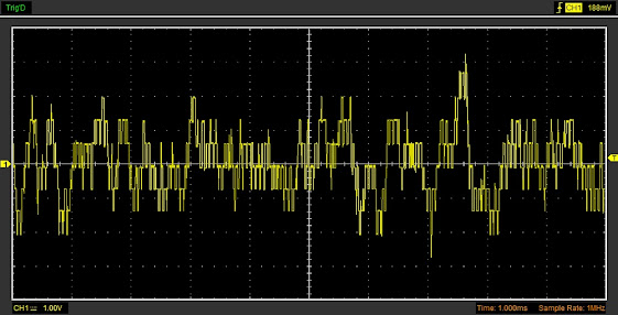
I used the Hantek 6022BE USB oscilloscope to record the output signal.
Testing showed that the power supply issue was not completely eliminated.
My 1.5 AA batteries were not fully charged. Charging the batteries will reduce the internal resistance.
Better results were obtained with 9 V batteries:
Figure 9: Two 9 V Batteries.
Conclusion
Testing showed that the power supply issue was not completely eliminated. This problem can be solved using high current mains powered 12 V or 9 V power supplies. Alternatively, connect one 9 V battery for each 556 timer IC. This would require five 9 V batteries or five 1.5 AA battery blocks. This solution is expensive. A better option is to use the main power supply.
What you should not do is connect a capacitor across the battery terminals. This might cause the capacitor to explode, especially if you are using a 12 V battery.
The appendix includes the Matlab file that was used to predict the oscillating frequency of the 555 timers. I used Octave software which is free to use.
Appendix
clear all;close all
R1=1000;
R2a=1000;
R2b=1*10^6;
R2min=R2a;
R2max=R2a+R2b;
C=32*10^-9;
MinFreq=1.44/(C*(R1+2*R2max));
MaxFreq=1.44/(C*(R1+2*R2min));
disp(['R1 = ' num2str(R1)])
disp(['R2a = ' num2str(R2a)])
disp(['R2b = ' num2str(R2b)])
disp(['C (nF) = ' num2str(C*10^9)])
disp(['Minimum Frequency = ' num2str(MinFreq) ' Hz'])
disp(['Maximum Frequency = ' num2str(MaxFreq) ' Hz'])


Comments
Post a Comment